|
K.C.S.E Physics Q & A - MODEL 2019PP2QN13
State the disadvantage using a convex mirror as a driving mirror
answer
0 Comments
K.C.S.E Physics Q & A - MODEL 2017PP2QN09
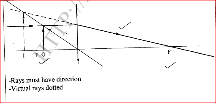
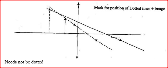
Figure 2 shows a virtual image I formed by a convex lens.
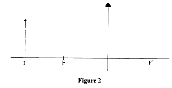
Draw a ray diagram to locate the object.
answer
K.C.S.E Physics Q & A - MODEL 2017PP2QN05
State two advantages of using convex mirrors to monitor movements in a large supermarket.
answer
K.C.S.E Physics Q & A - MODEL 2016PP2QN05
State the reason why a convex mirror is preferred over a plane mirror for use as a driving mirror.
answer
State the reason why a convex mirror is preferred over a plane mirror for use as a driving mirror.24/7/2020
K.C.S.E Physics Q & A - MODEL 2015PP2QN05
State the reason why a convex mirror is preferred over a plane mirror for use as a driving mirror.
answer
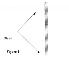
K.C.S.E Physics Q & A - MODEL 2015PP2QN01
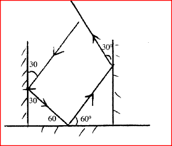
Figure 1 shows three mirrors arranged at right angles to each other. A ray of light is incident on one of the mirrors.
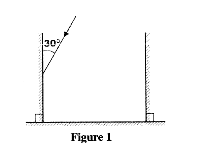
Complete the diagram to show the path of the ray after reflection on each of the mirrors.
answer
K.C.S.E Physics Q & A - MODEL 2014PP2QN018
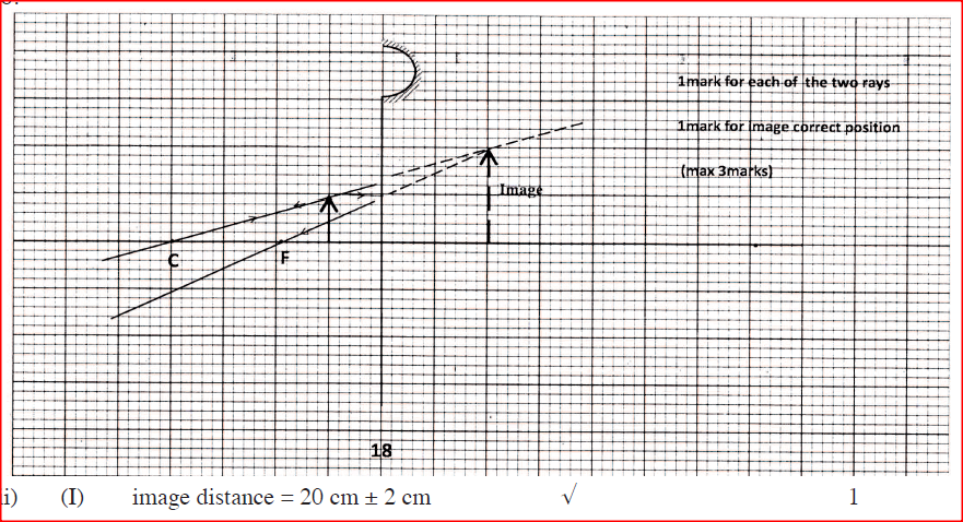
Figure 11 shows an object placed 10cm infront of a concave mirror whose radius of curvature is 40 cm.

(a) (i) On the same figure, draw a ray diagram to show the position of the image formed.
(ii) Use the ray diagram to determine: (I) the image distance. (II) the magnification. (iii) State where the position of the image would be if the object had been placed at the principal focus. (b) Draw a ray diagram to show the formation of a partially dark shadow and a totally dark shadow during the eclipse of the sun.
answers

K.C.S.E Physics Q & A - MODEL 2014PP2QN01
Figure 1 shows two parallel rays from a distant object passing through a convex lens:

(a) Indicate on the diagram, the position of the principal focus of the lens.
(b) Determine the focal length of the lens.
answers

(b) Focal length = 10 cm.
K.C.S.E Physics Q & A - MODEL 2013PP2QN14
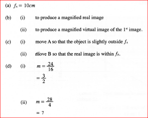
Figure 6 shows two convex lenses A and B used to produce a magnified virtual image of an object.

(a) Determine the focal length of lens A. (Take unit to represent 10cm).
(b) State the function of: (i) lens A (ii) lens B (c) State how the functions in (b) are achieved by: (i) lens A (ii) lens B (d) Determine the magnification produced by: (i) lens A: (ii) the whole system.
answers
K.C.S.E Physics Q & A - MODEL 2013PP2QN05
Figure 2 shows the image of an object formed by reflection in a converging mirror. C is the centre of curvature of the mirror

Complete the diagram to show:
(a) how incident rays are reflected to form the image; (b) the object position.
answer

K.C.S.E Physics Q & A - MODEL 2013PP2QN02
Explain why the image formed in a pin hole camera gets blurred when the hole is enlarged.
answer
K.C.S.E Physics Q & A - MODEL 2013PP2QN01State the reason why when a ray of light strikes a mirror at 900, the reflected ray travels along the same path as the incident ray.
answer
K.C.S.E Physics Q & A - MODEL 2012PP2QN017
(a) Figure 16, shows a graph of magnification against object distance, for an object placed infront of a lens of focal length 20cm.

Using the graph;
(î) State the effect on the size of the image as the object distance is increased from 25cm. (ii) Determine the distance between the object and the lens when the image is the same size as the object. (iii) Determine the image distance when the object distance is 25 cm. (b) Figure 17 shows an object O placed in front of a converging mirror of focal length 15cm. 
Draw on the figure a ray diagram to locate the image formed.
(c) State why parabolic reflectors are used in car headlights.
answers


(c) A bulb/lamp placed at principal focus will give a wide parallel beam;
K.C.S.E Physics Q & A - MODEL 2012PP2QN09
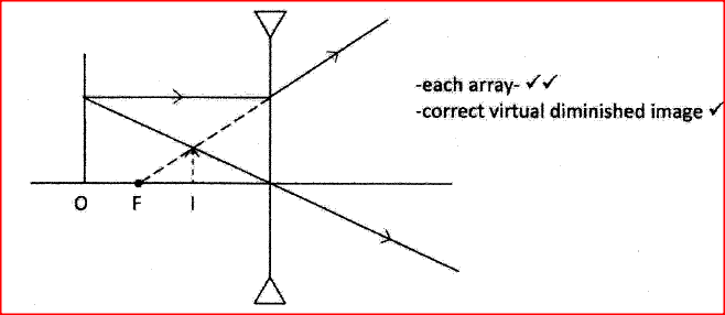
Figure 8, shows an object O placed infront of a diverging lens whose principal focus is F
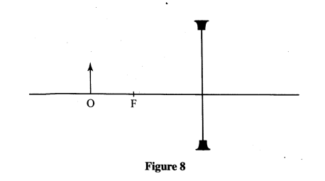
On the figure, draw a ray diagram to locate the image formed.
ANSWER
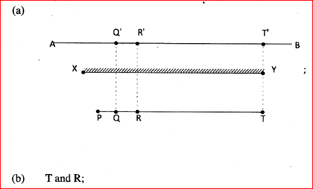
K.C.S.E Physics Q & A - MODEL 2012PP2QN01
Figure 1, shows a plane mirror XY placed equidistant from two parallel lines AB and PT.

Four students stand at P, Q, R and T in front of the mirror
(a) Indicate the positions of the images of students at Q, R and T on line AB. (b) State which of the images are visible to the student standing at P. (c) Using rays indicate on the figure, how (b) above is possible.
answers

K.C.S.E Physics Q & A - MODEL 2011PP2QN16
(a) State the meaning of the term “principal focus” as applied in lenses.
(b) You are provided with the following apparatus to determine the focal length of a lens: - a biconvex lens and lens holder. - alit candle. - a white screen. - a metre rule
(i) Draw a diagram to show how you would arrange the above apparatus to determine the focal length of the lens
(ii) Describe the procedure you would follow. (iii) State two measurements that you would take. (iv) Explain how the measurements in (iii) would be used to determine the focal length. (c) An object is placed 30cm in front of a concave lens of focal length 20cm. Determine the magnification of the image produced.
answers
(a) The point at which rays close to and parallel to the principal axis converge or seem to diverge from after striking the lens;

(ii) Candle is placed at a certain distance from the lens. The distance between the screen and the lens is adjusted until a sharp image is focused on screen.
(iii) The distance of candle from lens (U) is measured; The distance of screen from lens (V) is also measured; 
K.C.S.E Physics Q & A - MODEL 2011PP2QN01
Figure 1, shows an object placed in front of a plane mirror.
Sketch the image of the object as seen in the mirror.
answer

K.C.S.E Physics Q & A - MODEL 2010PP2QN16
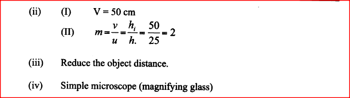
(a) Figure 10, shows an object placed in front of a converging lens of focal length 50mm
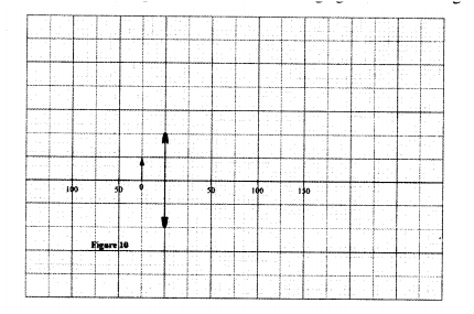
(i) On the same figure, draw a ray diagram showing the location of the image.
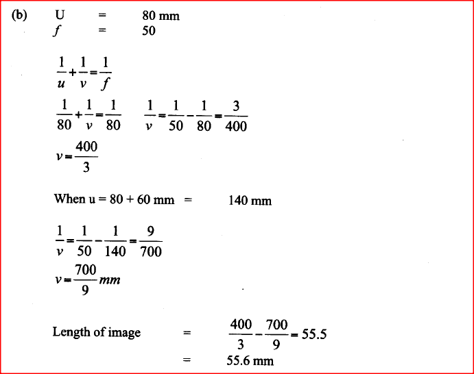
(ii) Use the ray diagram to determine the: (1) image distance; (II) magnification. (iii) State the adjustment that should be done to obtain a larger virtual image using the same lens. (iv) State one application of the arrangement in figure 10. (b) Figure 11, shows a pin 60 mm long placed along the principal axis of the lens used in part (a). The near end of the pin is 80 mm from the lens. 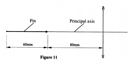
Determine the length of the image.
answers


K.C.S.E Physics Q & A - MODEL 2010PP2QN05
Figure 4, shows a bright electric lamp placed behind a screen which has a hole covered with a wire gauze. A concave mirror of focal length 25cm is placed in front of the screen. The position of the mirror is adjusted until a sharp image of the gauze is formed on the screen.
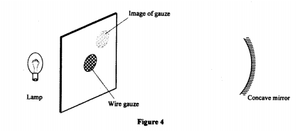
Determine the distance between the mirror and the screen.
answer
K.C.S.E Physics Q & A - MODEL 2010PP2QN01
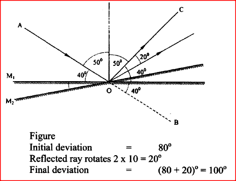
Figure 1, shows a ray of light incident on a plane mirror at O. The mirror is then rotated anticlockwise about O from position M1 to position M2 through an angle of 10°. The final reflected ray is OC
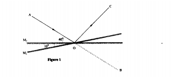
Determine the angle of deviation BOC
answer
K.C.S.E Physics Q & A - MODEL 2009PP2QN09
In an experiment, a pin a converging lens and a plane mirror are arranged as shown in figure 4. The distance between the pin and the plane mirror is L cm while the distance between the lens and the plane mirror is q cm. The position of the pin is adjusted until its tip coincides with its real image

State the focal length of the lens
answer
State the number of images formed when an object is between two plane mirror placed in parallel17/7/2020
K.C.S.E Physics Q & A - MODEL 2009PP2QN01
State the number of images formed when an object is between two plane mirror placed in parallel
answer
K.C.S.E Physics Q & A - MODEL 2008PP2QN05
The diagram in figure 2 shows an object O placed in front of a converging lens. F and F are the principal foci for the lens.

The object is now moved along the principal axis until a virtual image is produced.
On the same diagram: (i) Draw the object O in the new position along the principal axis; (ii) Sketch rays to show formation of the virtual image
answer
K.C.S.E Physics Q & A - MODEL 2007PP2QN04
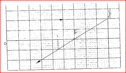
Figure 3 shows an object, O in front of a concave mirror and its image, I formed after reflection.
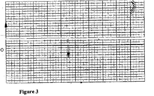
(a) On the same diagram draw appropriate ray (s) to locate the principal focus, F, of the mirror.
(b) Determine the focal length of the mirror (scale 1: 5)
ANSWER
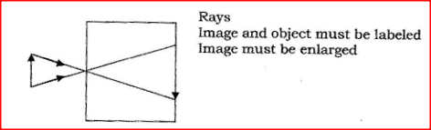
K.C.S.E Physics Q & A - MODEL 2007PP2QN01
Figure 1 represents a pinhole camera
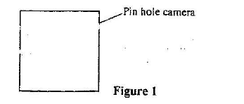
Sketch rays to show the formation of an enlarged image in the camera. Label both the object and the image
answer
|
CATEGORIES
Categories
All
Topics
FORM I - PHYSICS SYLLABUSFORM II - PHYSICS SYLLABUSTOPICS
FORM III - PHYSICS SYLLABUSFORM IV - PHYSICS SYLLABUSARCHIVES
RSS FEEDS
AUTHOR
M.A NyamotiMy passion is to see students pass using right methods and locally available resources. My emphasis is STEM courses
|
 RSS Feed