|
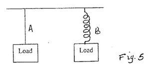
1. 1994 Q3a P2 (a) State Hooke's law (1 mark) 2. 1999 Q11 P1 A wire fixed at one end extends by 4mm when a load of 20N is suspended from the other end. Determine the load that would cause an extension of 1.5 mm on the wire (assume elastic limit is not exceeded) 3. 2002 Q10 P1 Fig. 5 shows a wire A and a spring B made of the same material. The thickness of the wire is the same in the both cases. Masses are added on each at the same intervals and the extension noted each time.
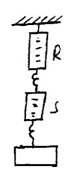
4. 2003 Q2 P1 Two identical springs balances R and S each weighing 0.5N are arranged as shown in Figure 2.
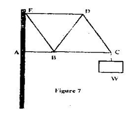
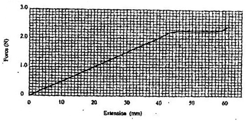
5. 2005 Q5 P2 (a) State Hooke’s law (1 mark) (b) One of a piece of a rubber was fixed to a rigid support and the other end pulled with a force of varying magnitude. The graph in fig 6 shows the relationship between the force (N) and the extension (cm) 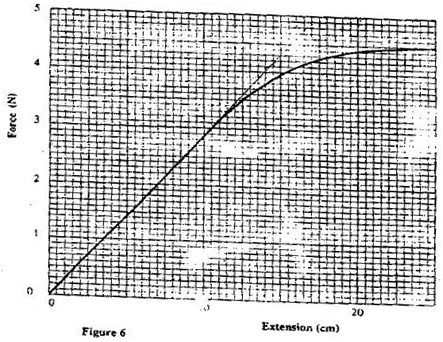 Using the graph, determine (i) The stretching force at the elastic limit (ii) The tensile stress in the rubber at an extension of 5cm if the cross-section of the rubber is 0.25cm2 (iii) The tensile in the rubber at an extension of 5 cm if the original length was 2m (3 marks) (c) In Fig 7. girders AB, BC, CD, ED, EB and BD were joined to make the rigid structure shown. The load W hangs from the structure as shown.
6. 2006 Q5 P1 The spiral springs shown in figure 4 are identical. Each spring has a spring constant k = 300N/m
7. 2006 Q15 P1 (a) You are provided with two wires of same material and same thickness. Describe how you would make two spiral springs of different springs constants (assume that other apparatus to make springs are available). (2 marks) (b) In an experiment, two identical springs are attached end to end. One end of the combined springs is fixed to a rigid support such that the spring hangs vertically. Masses are then hang from the lower end. The graph in figure 1 shows the relation between the force (weight) and the extension for the combined springs.
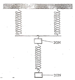
8. 2008 Q13 P1 The graphs in Fig. 7 represent the relations between extension e and mass m added on two springs x and y. 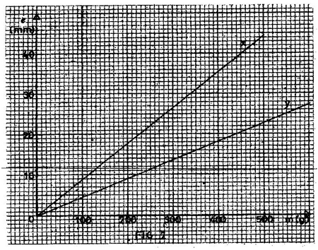 Fig. 7 Given that the two springs are made of same materials, give a reason why the graphs are different. (1 mark) 9. 2009 Q10 P1 The three springs shown in the figure are identical and have negligible weight. The extension produced on the system of springs is 20cm.
10. 2010 Q13 P1 State the SI unit of a spring constant (NB in words)(1 mark) 11. 2012 Q10 P1 Table 1 shows the result of an experiment carried out to study the properties of a spring.
3 Comments
George karuki
23/12/2020 09:31:01
Anwer of hooks law
yvonne
23/4/2021 20:20:26
good questions
Leo
28/1/2023 20:47:40
Extension is directly proportional to stretching force provided elastic limit is not exceeded Leave a Reply. |
CATEGORIES
Categories
All
Topics
FORM I - PHYSICS SYLLABUSFORM II - PHYSICS SYLLABUSTOPICS
FORM III - PHYSICS SYLLABUSFORM IV - PHYSICS SYLLABUSARCHIVES
RSS FEEDS
AUTHOR
M.A NyamotiMy passion is to see students pass using right methods and locally available resources. My emphasis is STEM courses
|


 RSS Feed