K.C.S.E Physics Q & A - MODEL 2004PP2QN05
a) Fig 6 shows a simple generator. The coils are rotated in the anticlockwise direction as shown
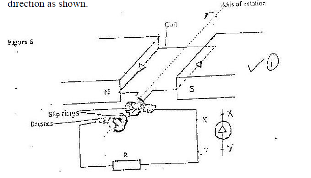
i) Indicate using an arrow on the figure, the direction of the induced current as the coil passes the position shown.
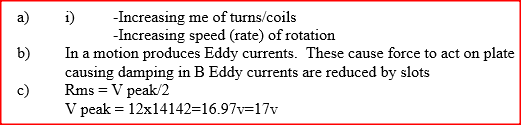
ii State two ways of increasing the magnitude of the induced current in this type of generator. iii) On the axes provided, sketch the graph of the induced e.m.f with time. iv) The section marked XY is cut off and a diode inserted. On the axes provided, sketch the graph of p.d across the resistor R, against time 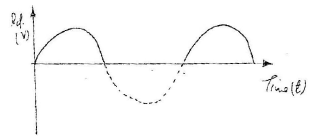
b) Fig 7 shows pendulum A and pendulum B freely suspended between the poles of identical magnets. Pendulum a is made of thick copper plate while B is made a copper plate with slot
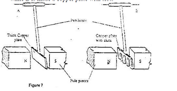
When the two are set to swing, it is observed that A slows down faster then B Explain this observation.
c) An alternating current source has a root-mean-square potential difference of 12,V, Determine the peak value of this potential difference.
answers
0 Comments
Leave a Reply. |
CATEGORIES
Categories
All
Topics
FORM I - PHYSICS SYLLABUSFORM II - PHYSICS SYLLABUSTOPICS
FORM III - PHYSICS SYLLABUSFORM IV - PHYSICS SYLLABUSARCHIVES
RSS FEEDS
AUTHOR
M.A NyamotiMy passion is to see students pass using right methods and locally available resources. My emphasis is STEM courses
|
 RSS Feed